Pipe sizing
Background
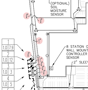
Pipe sizing specification on irrigation design drawing.
A maximum 5 feet per second (ft/s) water flow velocity is the industry standard for maintaining irrigation system integrity. Velocities above this rate can damage components, essential to the irrigation system’s operation.
Potentially damaging velocities correlate with smaller pipe diameters and, to a lesser extent, specific pipe material properties. The likely result of an incorrect pipe size is water hammer, which occurs when a wave of energy travels back and forth through the water in the pipe causing stress to the pipe, joint and adhesive holding the system together.
The graphic at right is taken from an irrigation design and depicts pipe-sizing specifications that would be reviewed to determine correct pipe sizing during a Florida Water Star evaluation.
Requirements and certification
Pipes are sized to prevent velocities greater than 5 feet per second (ft/s).

| Silver | Gold | Commercial/Institutional |
|---|---|---|
| Required | Required | Required |
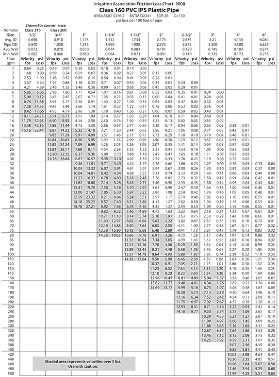
A friction loss chart is shown for Class 160 polyvinyl chloride (PVC) pipe. The shaded areas represent velocities over 5 ft/s, requiring a larger pipe to be used. Sizing tables are available in most irrigation system manufacturers’ catalogs.
Designers must size pipes according to a recognized pipe sizing/friction loss chart and clearly specify these pipe sizes on the irrigation system design. Installers must install pipes exactly as specified by design.

